Abit BH7 (Intel 845PE) Motherboard Review
Abit BH7 Features
This motherboard appears to be very compact (23 cm x 30 cm) and is made on orange PCB.
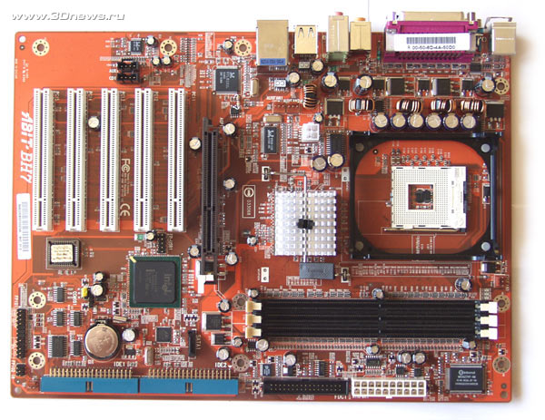
The board's design leaves a good impression: the main power socket is under the DIMM slots. That means the cables won't run loose inside the case and hinder the assembly. But the additional connector is positioned closer to the board's center, which is not the most important thing.
There are four sockets for plugging in fans on the BH7 board: the CPUFAN1 is positioned near the socket and is meant for the processor cooler.
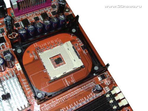
Two more connectors (AUXFAN1 and AUXFAN2) are positioned close to the North Bridge, with the last one (SYSFAN1) in the board's bottom left corner. Connecting and disconnecting fans is a breeze (I remember complaining much just about that when testing the IT7-MAX2 v2.0 board).
To cool the chipset, a passive radiator is used.
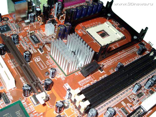
Below the North Bridge there are 3 DIMM slots, and the maximum memory capacity is 2 GB (restricted by the chipset).
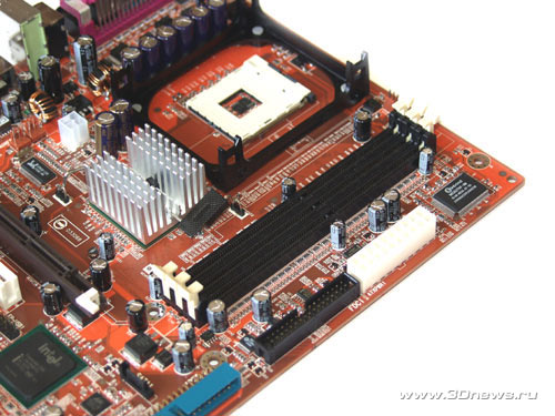
Once power is applied to the board, a yellow LED near main power socket lights up. When the board starts up, a red LED also lights up.
It's nice to note that an AGP video card does not block the latches of the DIMM slots. As for the AGP slots, it supports only 1.5V AGP 4XX video cards (like all the other i845PE\GE-based motherboards).
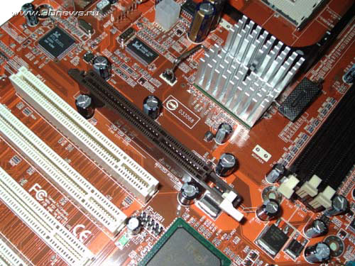
On the slot there is a special latch to keep the video card firmly in place.
Besides the AGP slot there are 5 PCI slots on the Abit BH7 motherboard.
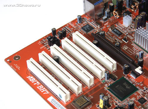
This number is quite enough for an entry-level system, especially if the board features 6-channel audio (ALC650) and an RTL8101 LAN controller.
Of course, there is support for the USB2.0 - six ports, four of which located on the rear panel with the other two are plugged in via a header (missing in the bundle). The header is plugged in to the FP-USB1 connector located near the PCI1 and PCI2 slots.
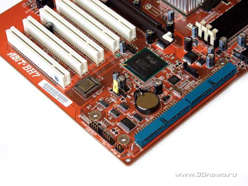
A couple of words on the disk subsystem. There is no integrated RAID controller on the BH7 board, but there is support for a SerialATA channel. To this end, there is a Marvell® 88i8030 controller on the board. Certainly, there is also support for the ParallelATA, as many as 4 devices can be plugged in to the integrated IDE controller. The respective connectors are painted in the same color (with explanatory captions as well) and are positioned in a pretty smart way - parallel to the board's plane.
This technical trick is used to facilitate plugging in the cables; in so doing the pressure during installation is uniformly distributed over the board's area, which doesn't result in its bending. By the way, we have seen such orientation of the IDE connector in the Asus P4PE board.
When plugging in a SerialATA device, you've got to keep in mind that the number of devices connected to the IDE2 channel is reduced (from two to one).
Now take a look at the board's rear panel.
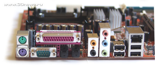
An absolutely nonstandard panel. Where the COM2 should be, there is an optical output, with four USB ports and a RJ45 port of the integrated LAN located further on.
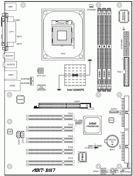
There is only one jumper on the Abit BH7 board - the CCMOS1 located near the battery cell and is meant for clearing the CMOS settings (or "BIOS reset"). The jumper has a plastic tail to make the switching easier; it's easy to find - the only yellow spot on the board :) (besides, there is a caption nearby). In fact, the quality of marking on the board is very good - all the captions are written in a large font, so they are easily seen inside the case.
Now on to the BIOS settings.
 |
Content: |
 |
|
 |
Top Stories: |
 |
 |
 |
MoBo:


|
 |
 |
 |
VGA Card:


|
 |
 |
 |
CPU & Memory:

|
|
|
