Asus P5LD2 Deluxe (Intel 945P)
Asus P5LD2 Board Features
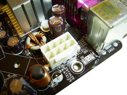
The specific feature of the board's design is the presence of two PCI Express x16 slots, as well as an additional 8-pin power connector:

unused connectors are closed with a plastic lid (which is removed)
Another additional connector (of Molex type) is positioned on the board's bottom end. Also there is the main 24-pin power connector.
For the assembly operator, the design won't be an issue since most problems related to connection of cables and installation of memory modules have been eliminated. The only possible issue may come from the inconvenient positioning of the SerialATA connector, and the additional RAID controller.
There isn't much to say about the socket itself - it is standard.
Beside it, there is a 4-pin connector (CPU_FAN) for a cooler. Besides it, there are three more 3-pin connectors: the PWR_FAN1 and CHA_FAN1 - near the north bridge, the CHA_FAN2 - near the BIOS chip. The board's design provides installation of two more 3-pin controllers: NB_FAN near the north bridge, and SB_FAN - near the south bridge. Evidently, engineers at Asus planned to arrange active cooling of the chipset, but then changed their minds and restricted to only the radiators.
Note that only two connectors (CPU_FAN1 and CHA_FAN1) offer support for the Q-Fan feature which allows adjusting the rotational speed depending on the temperature.
Under the north bridge, there are four 240-pin DIMM slots for DDR2 memory modules. They are partitioned into two groups, each having two slots. The first two slots refer to the first controller channel, with the other two to the second controller.
The board offers support for DDR2-400,533 and 667 memory; and the maximum capacity makes 4GB. Once voltage is applied to the board, a large green LED in the bottom-left corner of the board lights up.
There are two PCI Express x16 slots onboard (both with latches) which are meant for video cards.
This allows operating two nVidia video cards in the SLI mode at a time, and potentially - ATI Crossfire. But it should be noted that to the first slot 16 lines of PCI Express are rigidly allocated, with 4 lines left to the second slot. In so doing, the user can forcedly allocate 2 lines to this slot (using the respective parameter in the BIOS). As a result, one line is left for the PCI Express x1 slot, with one more line to the Gigabit Ethernet controller. Also, according the the preliminary tests, the performance difference for the SLI system in 8+8 modes versus the 16+4 is about 5-10%. Lastly, when installing two powerful video cards it is important to plug in a power cable to the additional onboard Molex connector.
Apart from the above listed slots, Asus P5LD2 has three more "regular" PCI slots.
 |
Content: |
 |
|
 |
Top Stories: |
 |
 |
 |
MoBo:


|
 |
 |
 |
VGA Card:


|
 |
 |
 |
CPU & Memory:

|
|
|
